Singapore
Summary
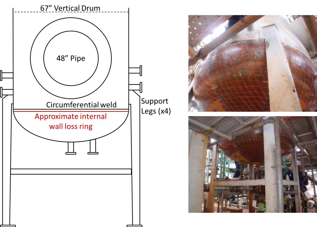
A 67” vertical knock-out drum suffered a system upset over three years ago resulting in a localized band of internal wall-loss near the entire circumferential dome weld. After performing initial defect assessments, it was determined that the pressure vessel could not operate at full capacity without suffering rapid through wall around the entire circumference. Additionally, the corrosion occurred beneath the lowest support meaning that a structural failure would result in the drum head detaching.
To provide a short-term remediation, a composite repair system was custom designed for the operator to address the three primary concerns: through wall leaking, internal pressure containment and preventing dome separation. Three unique systems were combined and used to achieve a successful repair for over 3 years while a replacement drum was ordered for the next turn-around. This case study will highlight the flexible design capabilities of composite materials in addressing critical component repairs when Engineered appropriately.
Introduction
In December 2015, CSNRI was contacted by a large international service company to review a vertical knock out drum with severe damage. The system had suffered an upset condition resulting in a ring of internal wall loss directly under the circumferential dome weld. After an assessment from the operator it was determined that the knock-out drum had to run at a greatly reduced capacity to prevent continued internal wall loss at an aggressive rate. Immediately, there were two primary modes of failures:
-
- Leaking Vessel - localized areas were expected to quickly reach through-wall conditions.
- Structural Failure - As can be seen in reference Figure 1, the support structure for this knock-out drum connects above the affected area. If sufficient wall loss occurs beneath this support, the bottom dome will detach causing severe structural failure.
The scope of this potential repair scenario was initially deemed outside of any current composite repair standards, primarily ASME PCC-2 or ISO 24817, and would require a custom design. After exhausting all other known repair methods as well as a replacement drum, the end-user requested a custom design to be considered. The final proposed design consisted of three unique composite systems that would be applied atop one another in separate stages:
- Inner system – tri-directional fiberglass weave designed primarily for leak containment.
- Middle system – unidirectional carbon fiber composite system with the sole purpose of holding the dome in place in the event of complete dome separation.
- Outer system – bidirectional carbon fiber composite system intended to minimize strain resulting from multi-directional stress forces.
Installation Considerations and Procedure
In addition to the Mathematical design, the physical constraints and geometric conditions need to be taken into consideration for the final design. The primary concerns can be broken into three areas:
- Integrating the many outlets and welded plates into the repair.
- Wrapping the bottom dome with two protruding nozzles.
- Integrating and wrapping around the welded support legs.
The following section will cover the general installation approach with a focus on the listed concerns.
Outlet / Nozzle Integration
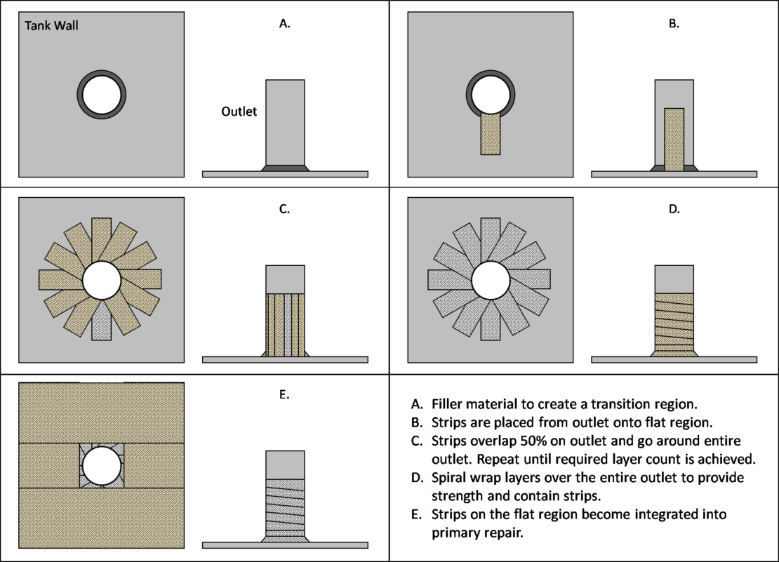
There were many outlets over the intended repair region that required a “tie-in” to ensure a consistently strong repair area. Generally, a smaller fabric width was utilized on these nozzles to provide structural support to the nozzle itself as well as to create a tie-in region. The drawings below show the general path taken for the nozzle tie-ins referenced throughout the remainder of the installation.
Support Leg Integration
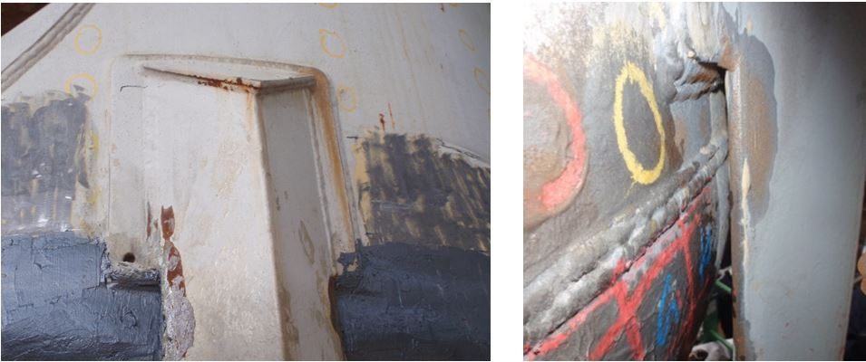
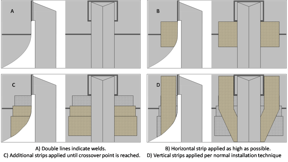
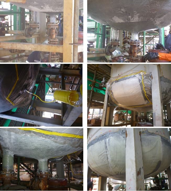
The construction and placement of the support legs provided a unique challenge in the installation due to the limited space available. The support leg was welded to the shell about 2-3 inches above the dome weld and 4-5 inches above the internal defect. Near the dome weld, only an inch of clearance was available. Ensuring a consistent, strong repair underneath the support leg was critical to the overall success. Throughout the various installation steps, a different procedure had to be followed to tie in the area beneath the support leg. After the initial four layers of FormaShield™ were vacuum bagged underneath the support leg, all the remaining layers were applied via vertical strips running up and down the drum. In regions covered by the support leg, this was not a possible and an alternate method of achieving the desired layer count had to be used. Primarily, short horizontal strips were placed underneath the support leg in a stacked sequence to achieve the required layer count. Vertical strips, per the original installation method, were than used to capture the horizontal strips securing them in place. Figure 2 shows images of the support leg as well as an example installation procedure.
Installation Steps
Initially, the dome was cleaned and prepared for inspection. After the initial inspection was performed and it was decided by the operator that a composite repair would be considered, an initial layer of adhesive primer was applied over all bare metal to prevent any external corrosion from occurring during the design of the repair and shipping of material. Due to this initial coating, the only surface preparation needed during the repair would be light surface abrasion with sandpaper on the primer and pneumatic tool work on any outlets or regions not previously cleaned.
The first stage of the repair consisted primarily of applying the FormaShield™ leak repair system onto the dome. The dome itself provided a unique challenge as it was not only vertical but also contained two outlets and was in a difficult to reach area. Considering the minimum calculated 10 layers for FomraShield™ to be installed, it was determined that the initial four layers would be applied with vacuum assistance to maximize the bond and adhesion to the substrate. In order to accommodate the vacuum patch application, individual 2-foot x 2-foot sections were installed systematically starting with the outlet tie-in location. Of note was the limited space under the leg support. Use of the vacuum bagging technique in this situation allowed for maximum compression in a region with limited access.
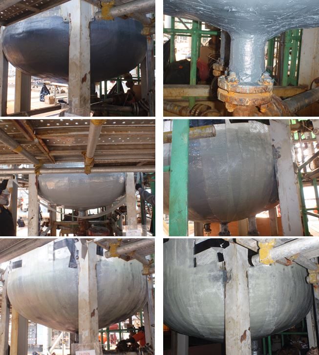
After the initial four layers were applied to the dome region, a new approach was used on the remaining six layers of FormaShield™ as well as the carbon fiber installation steps. To begin, all overlaps and transitional zones were smoothed using a load transfer filler. Long strips of FormaShield™ fabric were then wet-out and applied in systematic strips around the dome. Additional horizonal strips reinforced the area under the leg supports where vertical strips could not be applied. The individual strips were secured via mechanical means applied at the end of the strips until fully cured. The approach utilized resulted in 6 layers of FormaShield™ at the weld and significantly more layers near the bottom of the dome.
Once the FormaShield™ system had all 10 layers applied and fully cured, pneumatic tools were used to prepare the surface above the weld as well as trim the fiberglass system. Filler material was once again used to fill in all transition zones. The next repair to be installed was the RenewWrap™ carbon fiber system intended for vertical support to hold the dome in place. After the surface prep was verified using replica tape, adhesive primer was installed over the repair area. Using a similar installation procedure as the previous fiberglass installation, four layers of RenewWrap™ were applied extending far beyond the weld. No horizontal strips were used as they would not provide vertical structural reinforcement.
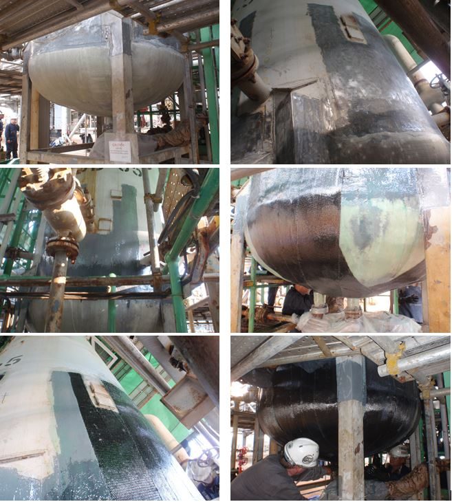
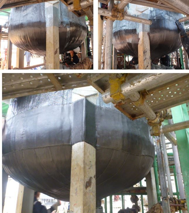
The final installation step comprised of the Atlas™ repair system. This bi-directional carbon fiber repair system was installed to support all hoop stress loads and to secure the repair to the support legs. Once more, filler material was used to fill in any transition spots. The Atlas™ system was applied with the same vertical strip placement technique but only went a few inches beyond the weld. After fours layers had been applied in this method, circumferential strips were placed to encompass the support legs and help secure the vertical strips in place higher on the drum. Once cured, the system was lightly abraded and coated for UV protection.
Conclusions
Utilizing a multi-stage approach, a composite repair was custom designed to fit the unique requirements for the customer. The installed composite repair must be able to prevent any leaks once the substrate is gone, maintain design pressures in a multi-stress environment and prevent dome separation. Additionally, the physical challenges to the installation itself included multiple nozzles, support legs and other obstructions all while being applied on a vertical surface in hot and humid conditions. The initial design life has been reached with the knowledge that the dome and main shell have completely separated due to corrosion and is only functioning due to the composite repair. Per the customer’s request, a second application was installed reaching further up the knock-out drum to provide additional safety as the original design life was extended by another two years.
The success of this repair in such an extreme scenario highlights the capabilities of composite repair systems. When properly designed and installed composite repairs can offer custom solutions to defect scenarios with no ready-made repair available. It is important, as always, to ensure that all reasonable considerations including temperature limits, cyclic conditions, chemical compatibility and operating conditions are taken into consideration by a knowledgeable group of Engineers who can demonstrate sound engineering and material science. While no single composite repair is a “fix-all” for every defect, well-designed composite repairs can be of tremendous use in unique situations.

